CISCA-Uniform load test
CISCA Uniform load testing Setup
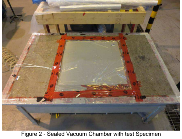
The specimens were tested in accordance with CISCA 2007, Section .7. Prior to testing the samples were placed on to a frame built to simulate rigid, continuous perimeter stringers supported by four pedestals as shown in Figure 1.
The frame consists of four 50 mm x 100 mm x 570 mm (nominal) length wood with four 50 mm x 100 mm x 325 mm (nominal) height wood pedestals. Each member was connected and braced using a 90°, 4″ wide metal bracket and fastened together with zinc coated No. 8 -2-1/2″ Robertson screws.
Each gauge was placed within the metal pressure chamber and connected to the underside of each specimen in order to measure the following:
• Center Deflection
• Mid-span Edge Deflection
• Weakest Point Deflection (identified as the center)
Deflection and pressure measurements were recorded by a data acquisition system at 1-second intervals.
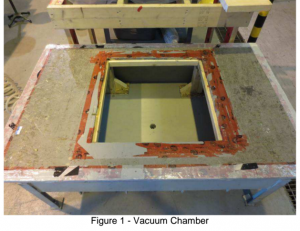
Using the vacuum method as prescribed in ASTM E2322-03(2009) Section 10, each specimen was placed inside the pressure chamber and covered with a 3 mil POLYTARP plastic sheet to provide an air tight blanket over the specimen.
The perimeter of the plastic sheet was taped with Tuck TapeTM to complete the seal as shown in Figure 2.
Each panel was subjected to a 50 lb./ft^2 (2.39 kPa) preload and tested at increments not exceeding 300 lb./ft^2.(14.36 kPa) with the initial load no more than half of the test load, the rate of load not exceeding 37.5 lb./ft^2 (1.76kPa) per minute.